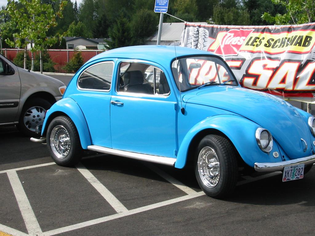
This is a series of photos showing the installation of the CB
Performance Quick-Tune EFI in Andy's 1966 VW Bug. The
EFI is a complete kit (minus fuel line plumbing). This replaces a
pair of Weber IDF 40's, which were too restrictive at higher rpms
for an engine this size, even with larger 32mm venturis.
Engine Specs:
- 2110cc (90.5mm x 82mm)
- 1.5" exhaust with heater boxes, ceramic coated
- CB Performance 044 SuperMag heads with 42x37 valves, single
valve spring (I'll get dual springs if I ever upgrade the heads)
- Hydraulic lifters (nice and quiet!)
- Weber Cam 533H - 268° duration, 0.350" lift.
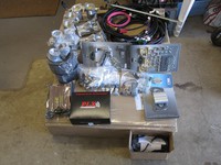
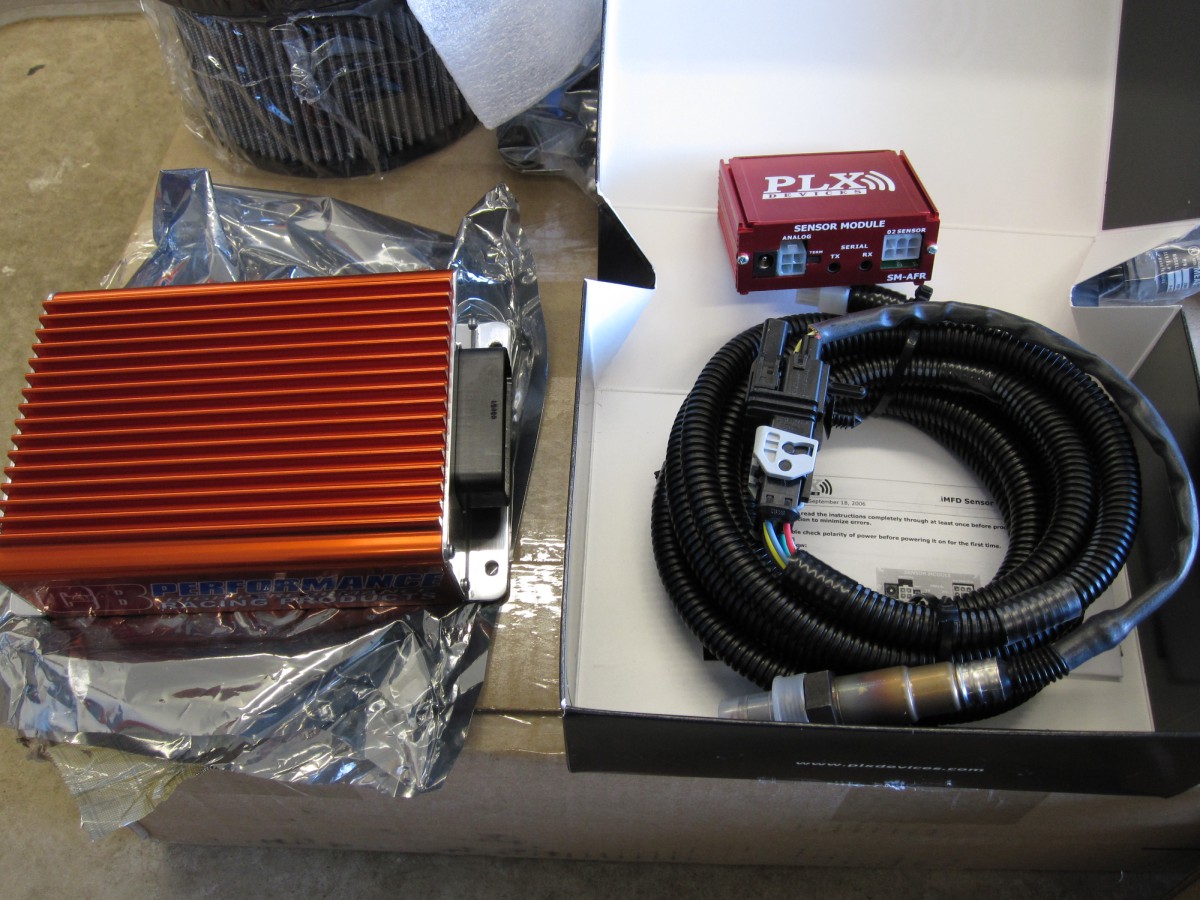
The CB Quick Tune kit. It's very complete.

The brain box and O2 sensor. No extra relay
board is needed.
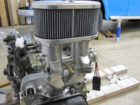
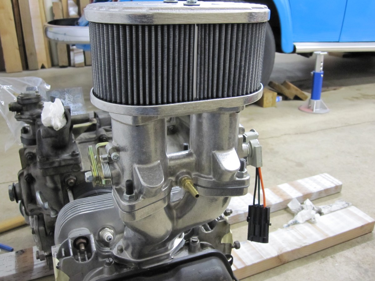
Test fitting the intake manifold and throttle body
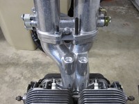
Test fitting the intake manifold and throttle body, another view.

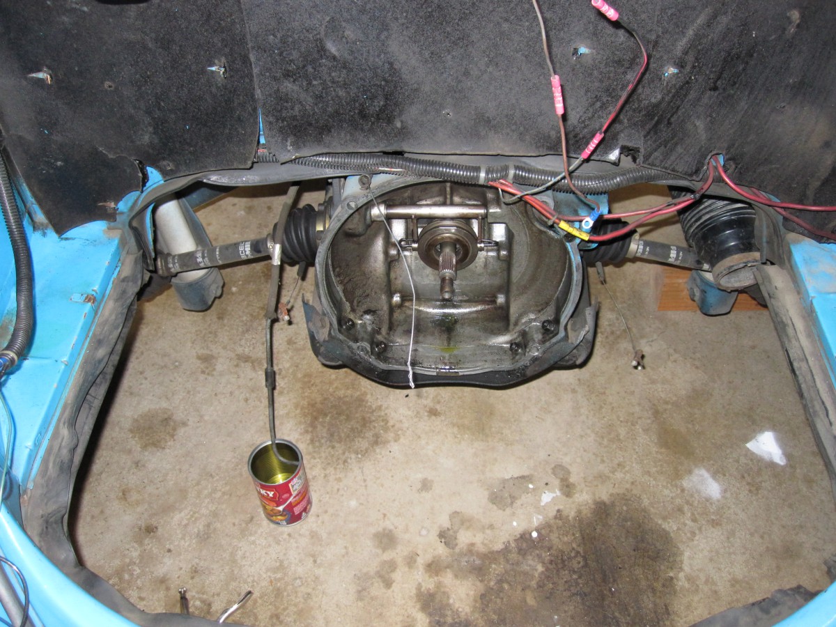
I removed the engine so I would have room to work.
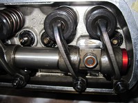
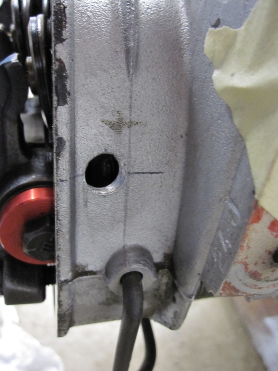
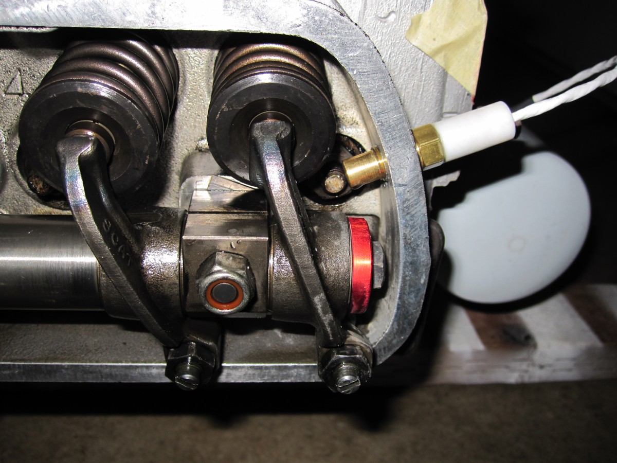
Prep for Cylinder Head Temperature (CHT) sensor, which is mounted
in head near #4 cylinder

Hole drilled and tapped for the CHT sensor.
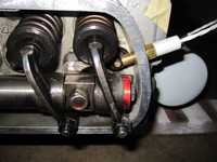
CHT sensor mounted, checking rocker arm clearance.
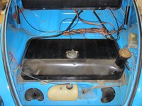
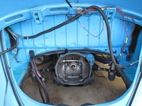
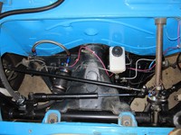
Trunk area, getting ready to remove fuel tank. 1966 body on a 1970
pan. 12 volt electrical system.
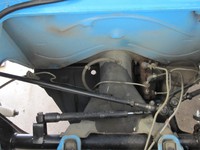
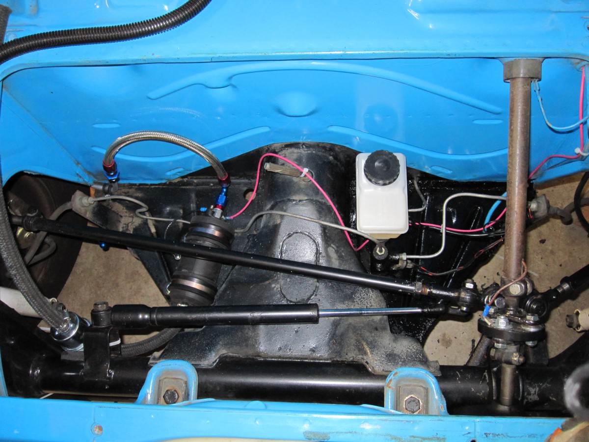
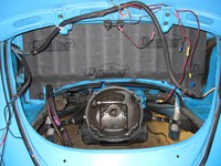
Fuel tank removed. I ended up replacing the brake fluid reservoir
with one that mounts on the master cylinder - see later photos.
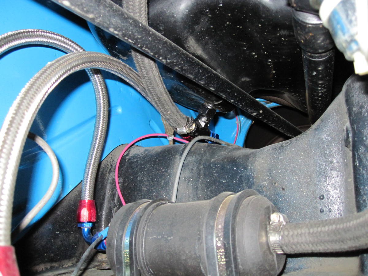
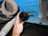
Locating the new electric fuel pump near the fuel tank.
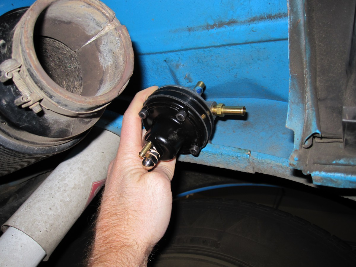
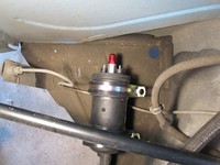
Locating the fuel pressure regulator (FPR) - CB says this should
NOT be mounted in the engine compartment due to heat.
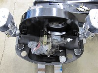
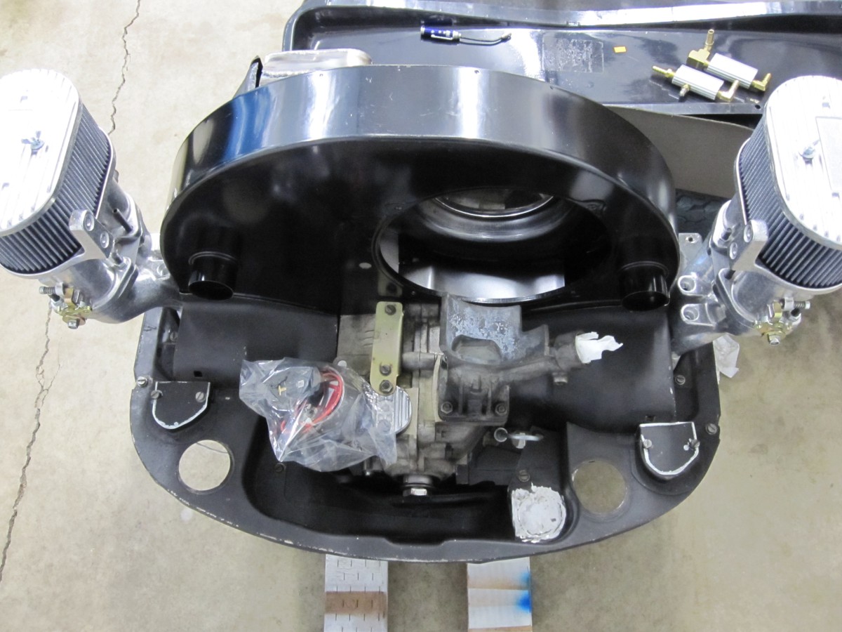
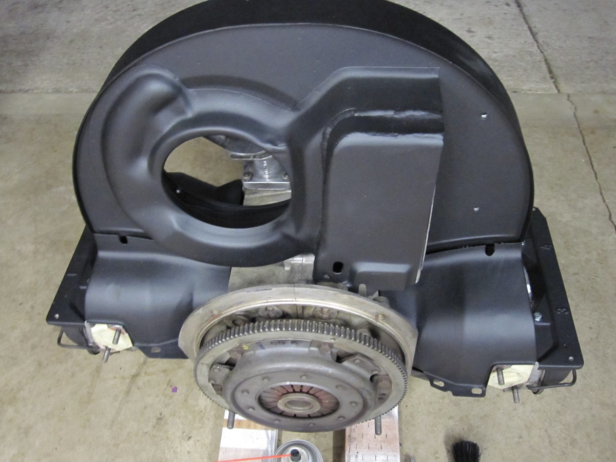
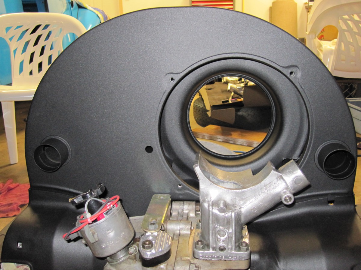
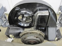
Trial fitting a new "36hp" style fan shroud needed to clear
injectors.
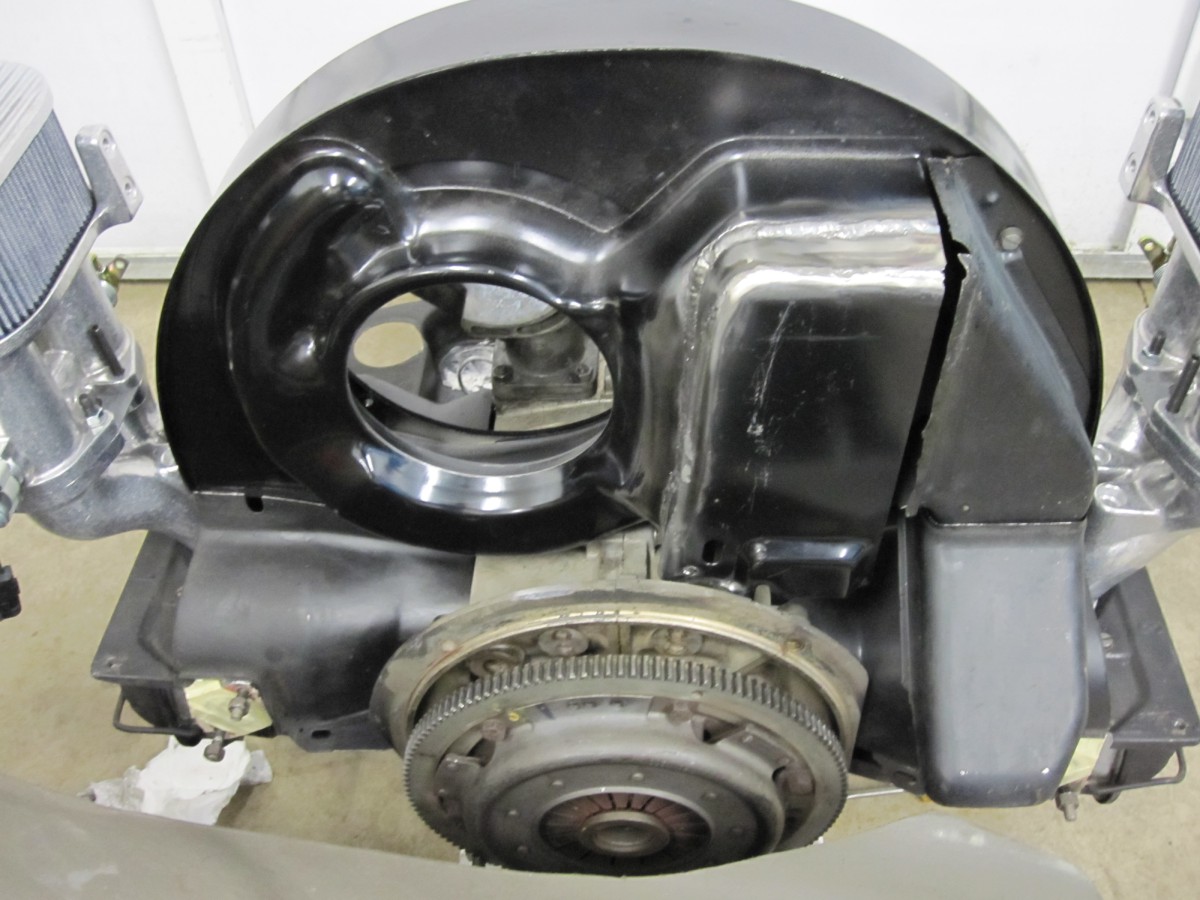
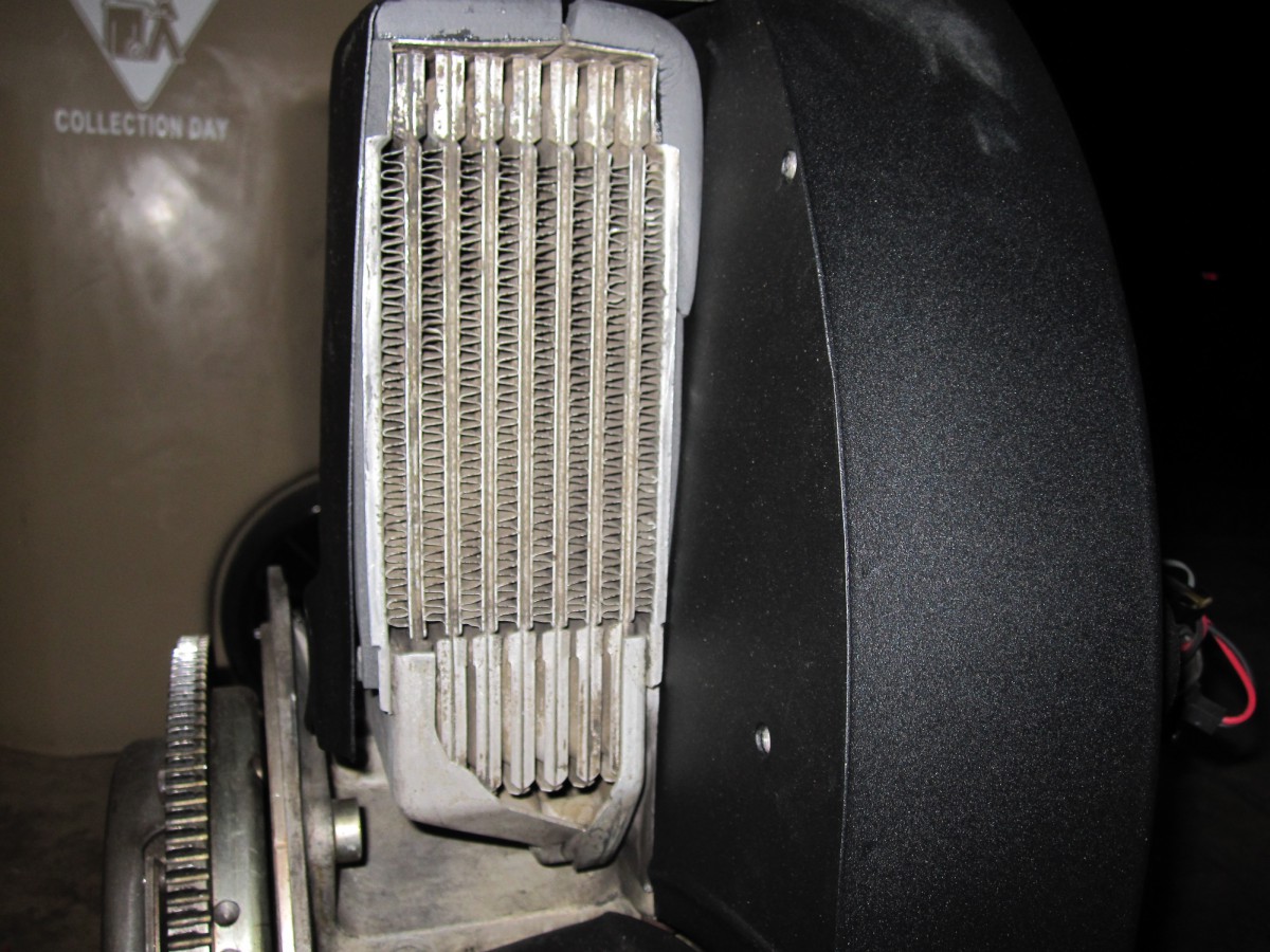
The oil cooler ducting needs about a 1/2" extension to clear a
Type 4 oil cooler.
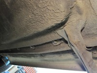
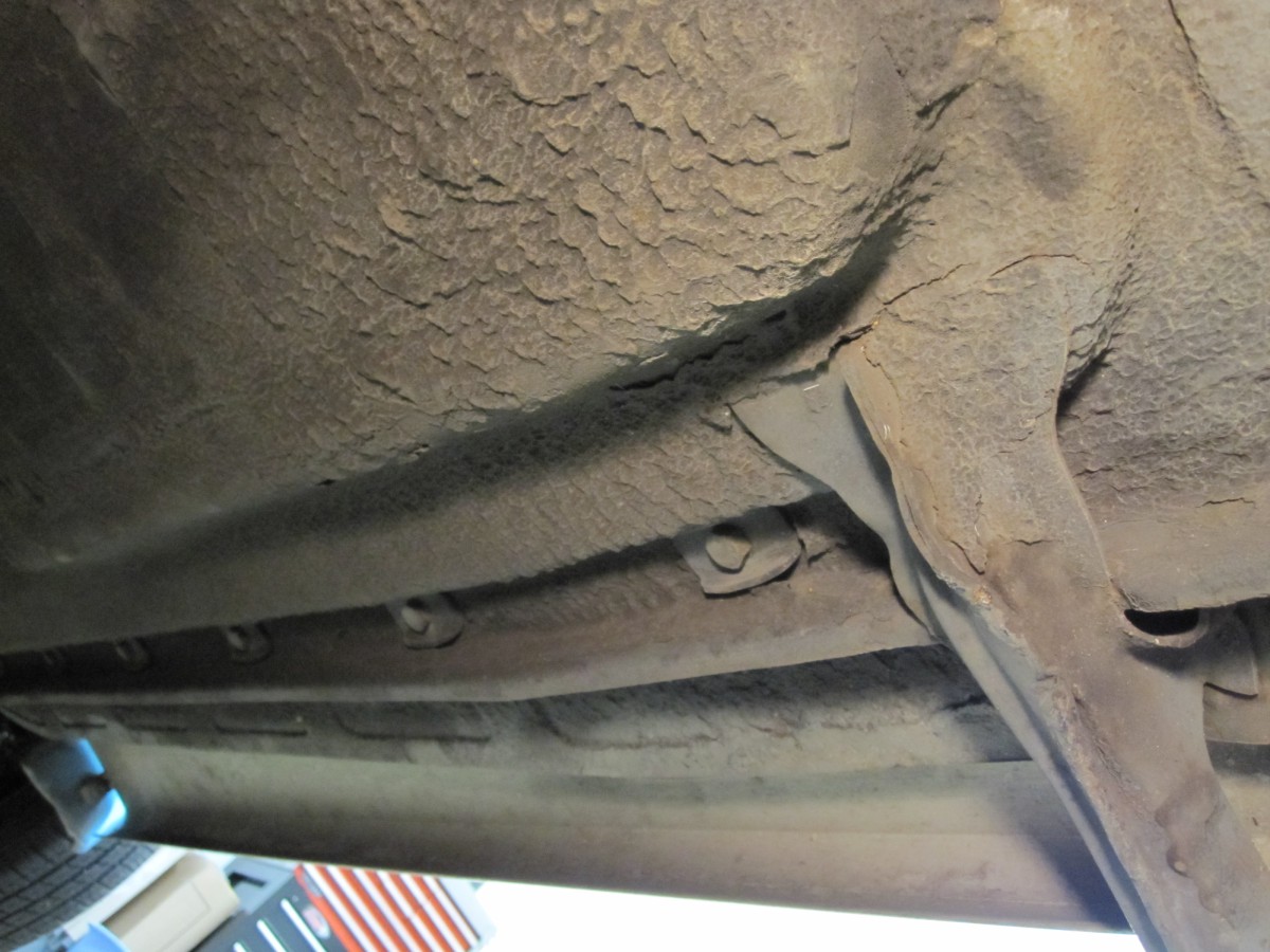
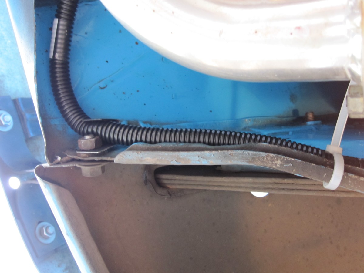
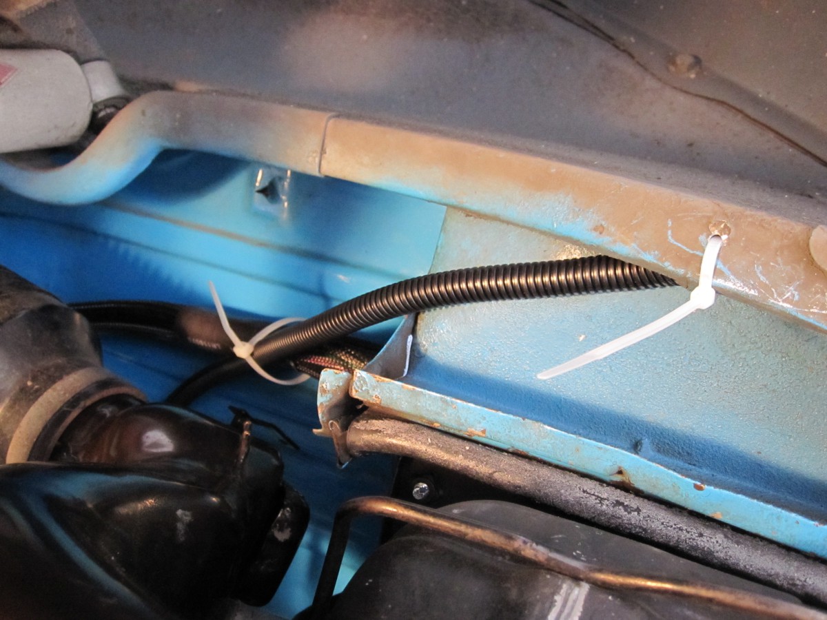
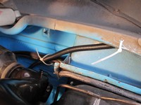
Going to route two 3/8" steel fuel lines underneath in this
channel for protection.

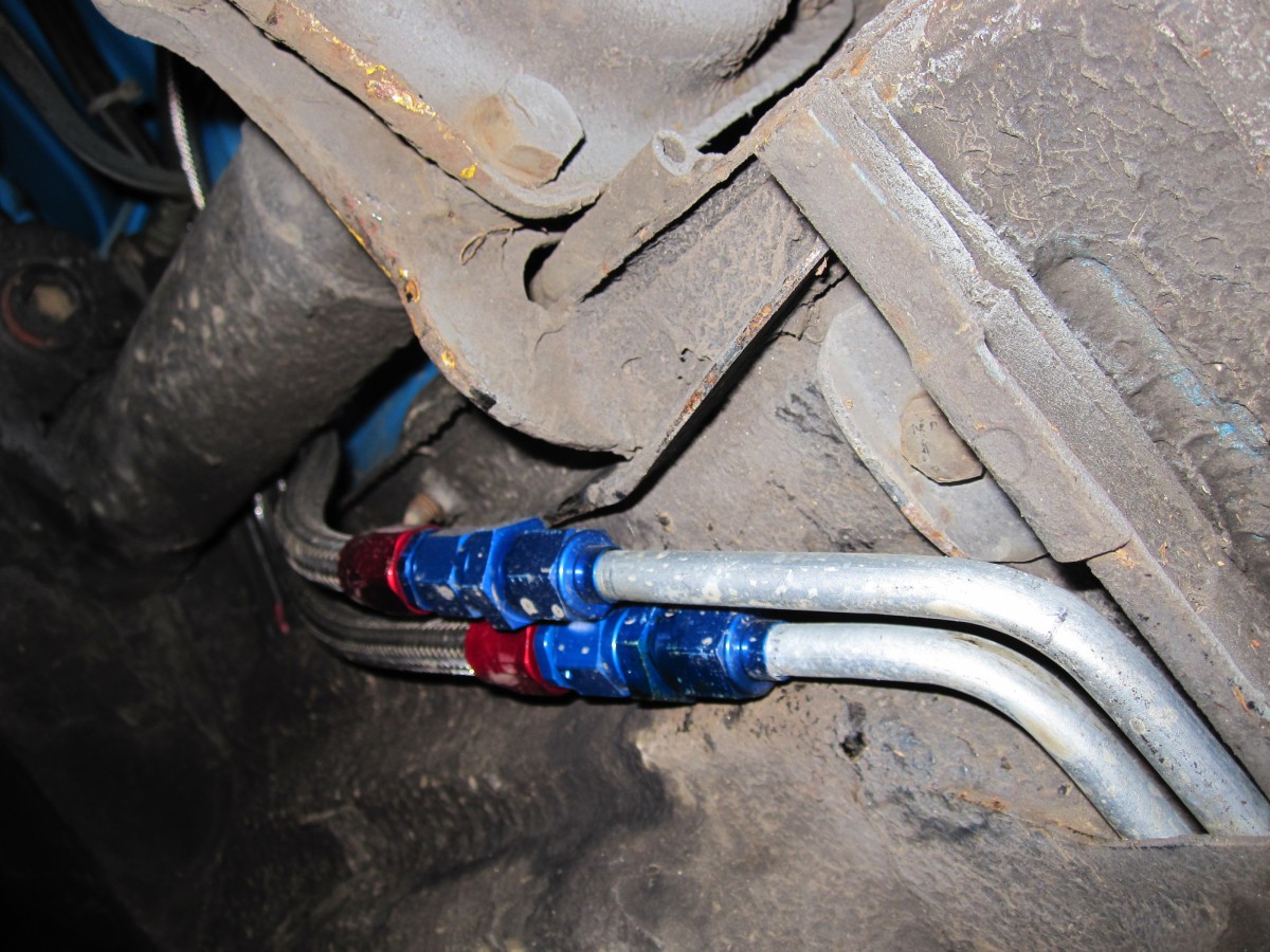
Hardline exits the channel and converts to flex hose in the back -
much easier to route.
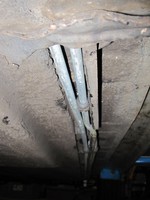
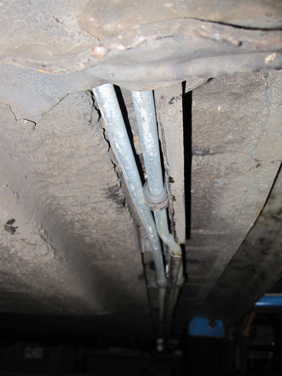
Stainless hose clamps bolted to the channel.

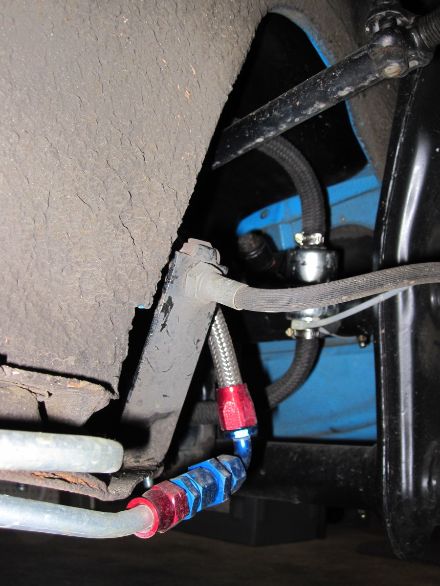
Hardline converts to flex hose in the front too.

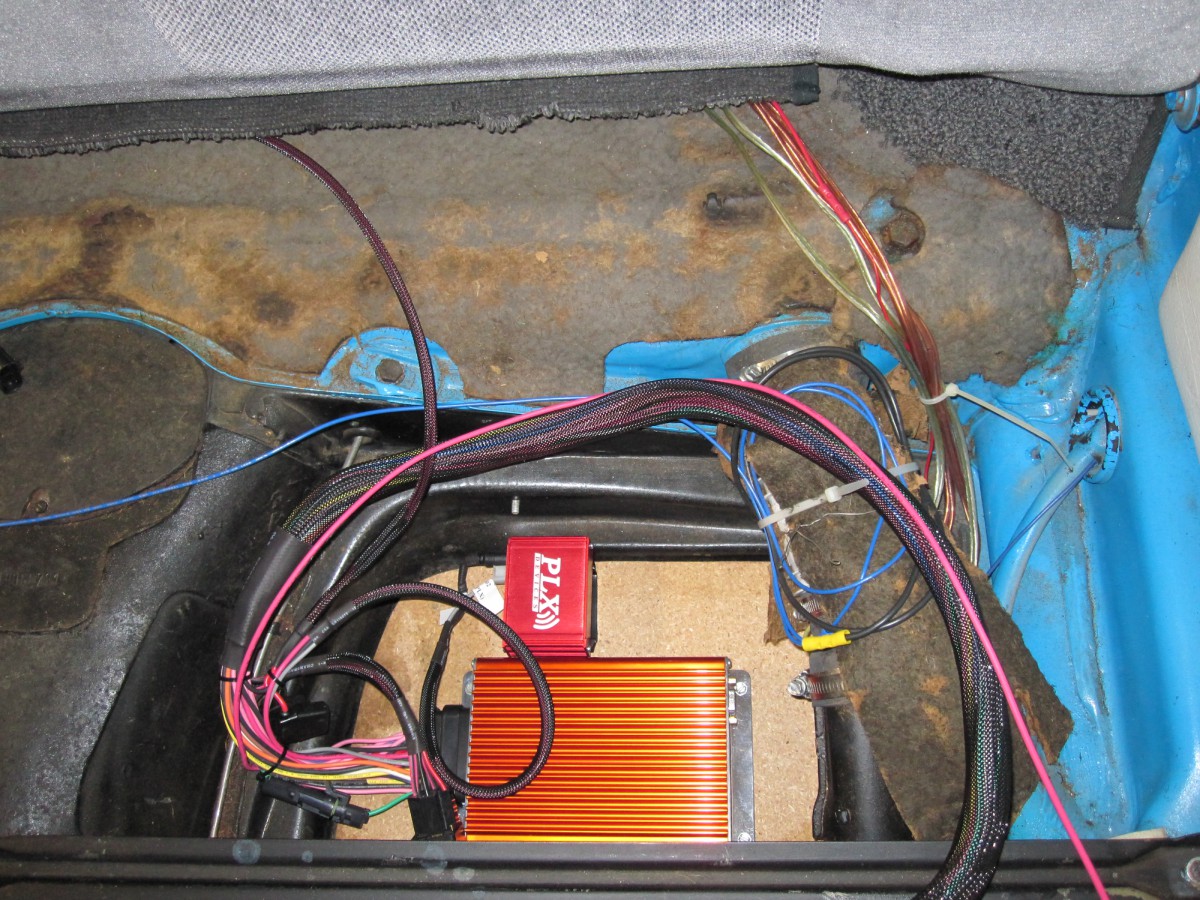
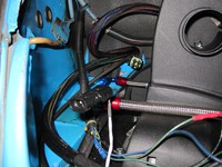
The electronics went underneath the rear seat (CB "brain box" and
O2 sensor electronics).
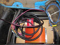
Big hole drilled and wiring laid out. Coil the excess
length, don't cut wires.
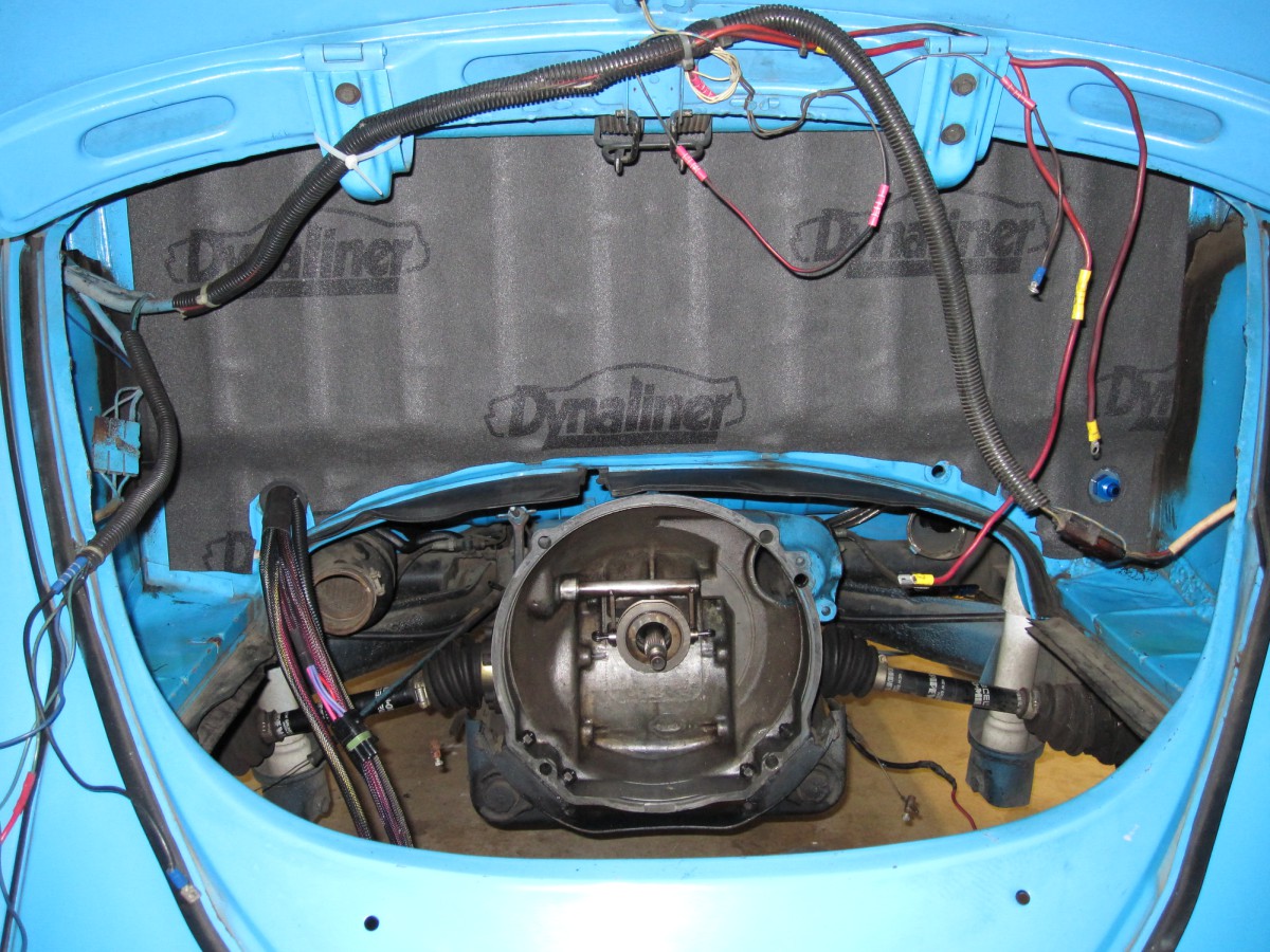
Engine compartment has been cleaned up. I got rid of the old tar
boards.
Dynaliner sound deadening installed.
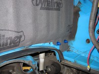
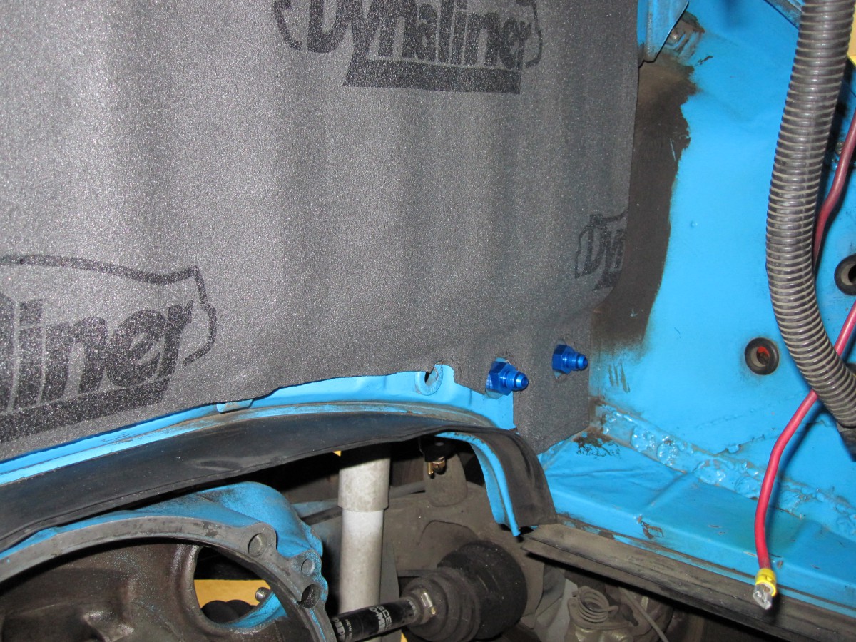
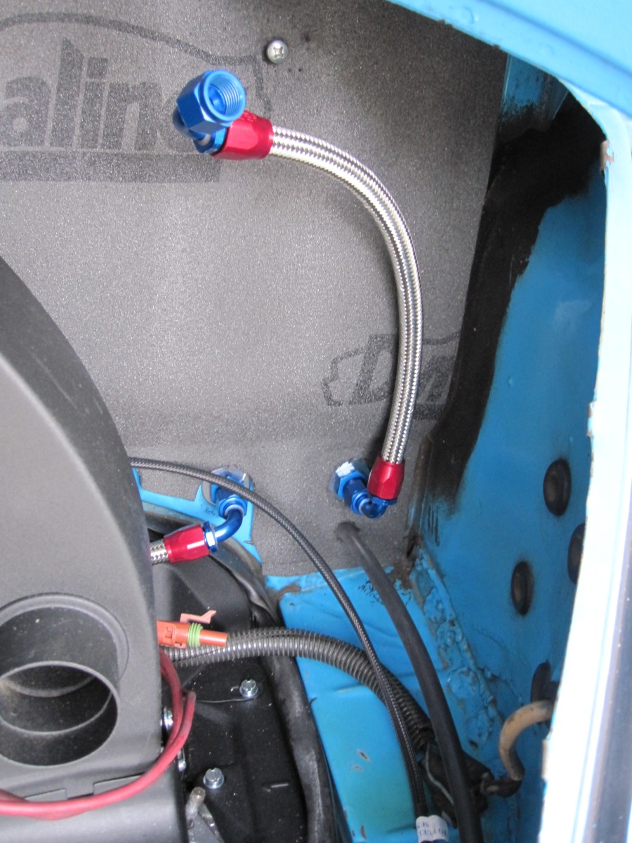
Fuel supply and return bulkhead fittings on passenger side.
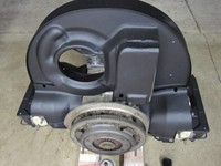
Engine tin powder-coated flat black.

Engine tin powder-coated flat black.
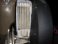
Type 4 oil cooler with foam sealing strips to prevent air leaks.
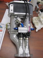
Fuel injectors, fuel rail, and pressure gauge installed to
throttle bodies.

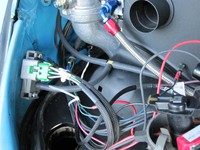
Fuel injector wiring has to be routed this way or it will
interfere with the fan shroud.

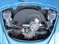
Trial fit in engine compartment. It's close!
There are a lot of wires on the driver side!

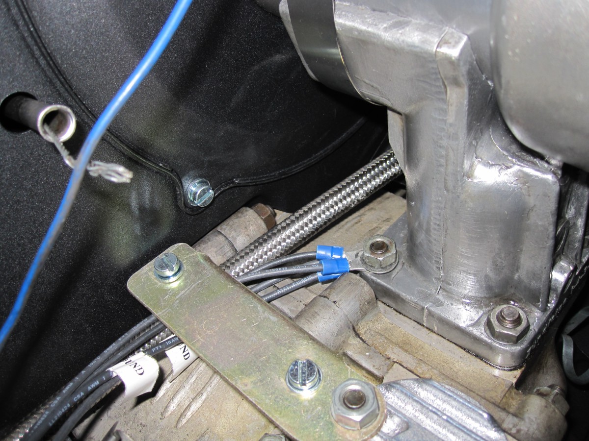
Ground wires should be attached to a single, common point on the
engine case.

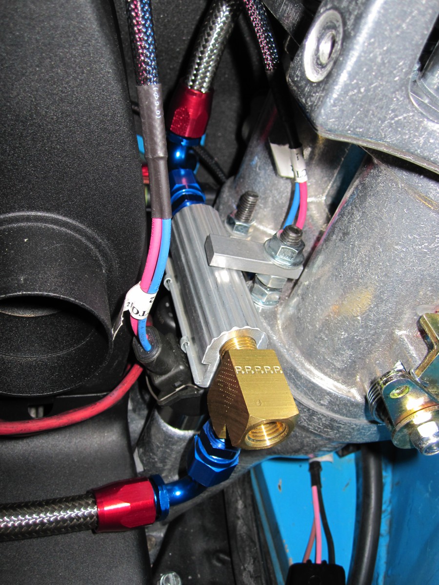
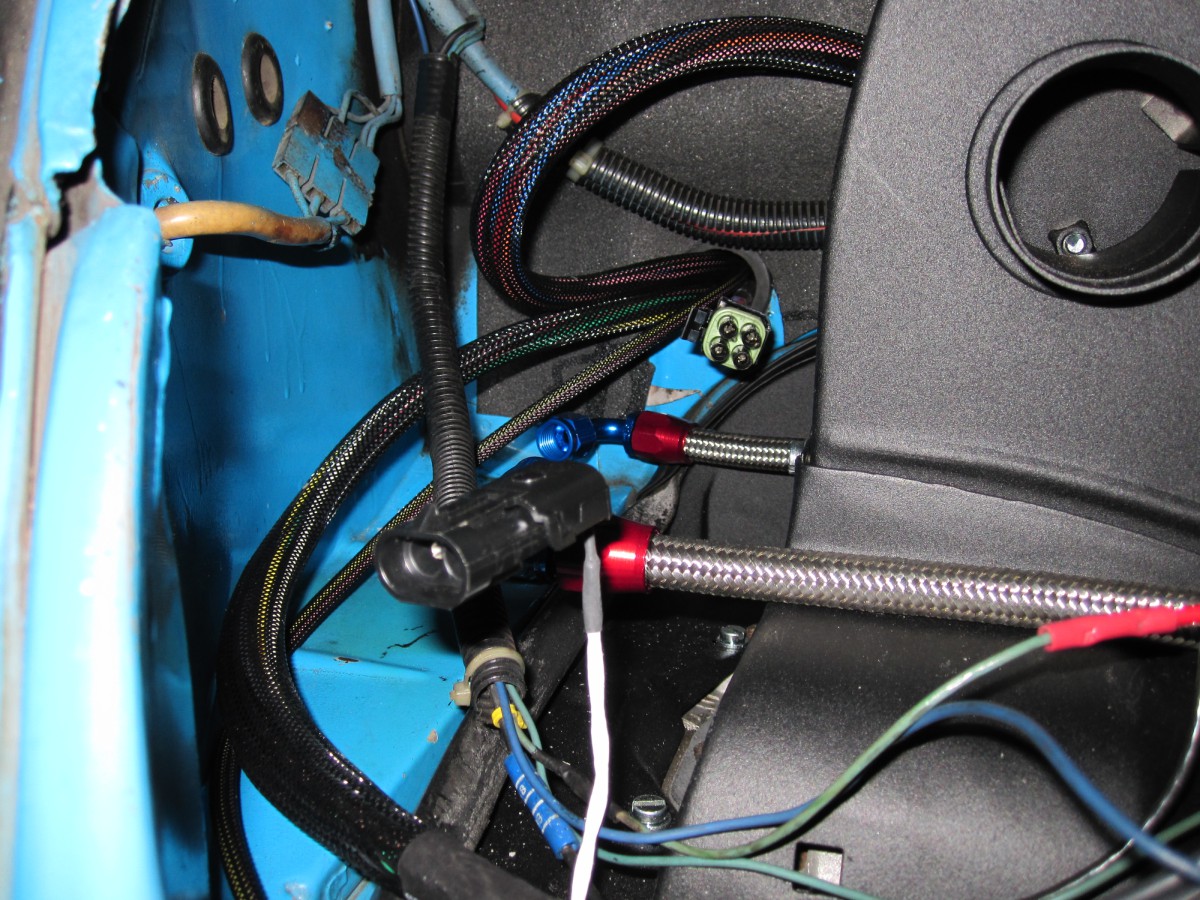
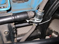
Fuel supply and return lines. Vacuum line goes to FPR behind the
wheel well.
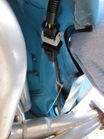
The O2 sensor goes in the exhaust and the cable attaches to the
rear apron.

Routing the O2 sensor cable along fender well.
And up along with main wiring harness to rear seat area.
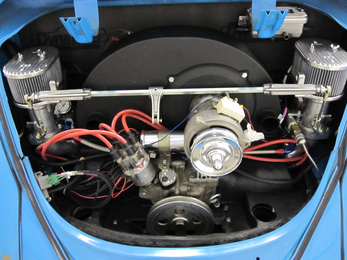
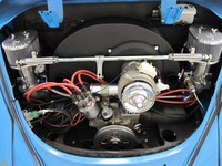
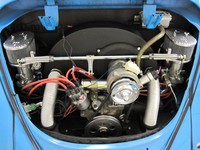
Showing throttle bodies installed with fuel and vacuum lines
connected.
Close-up view of MAP sensor showing where I decided to mount it.

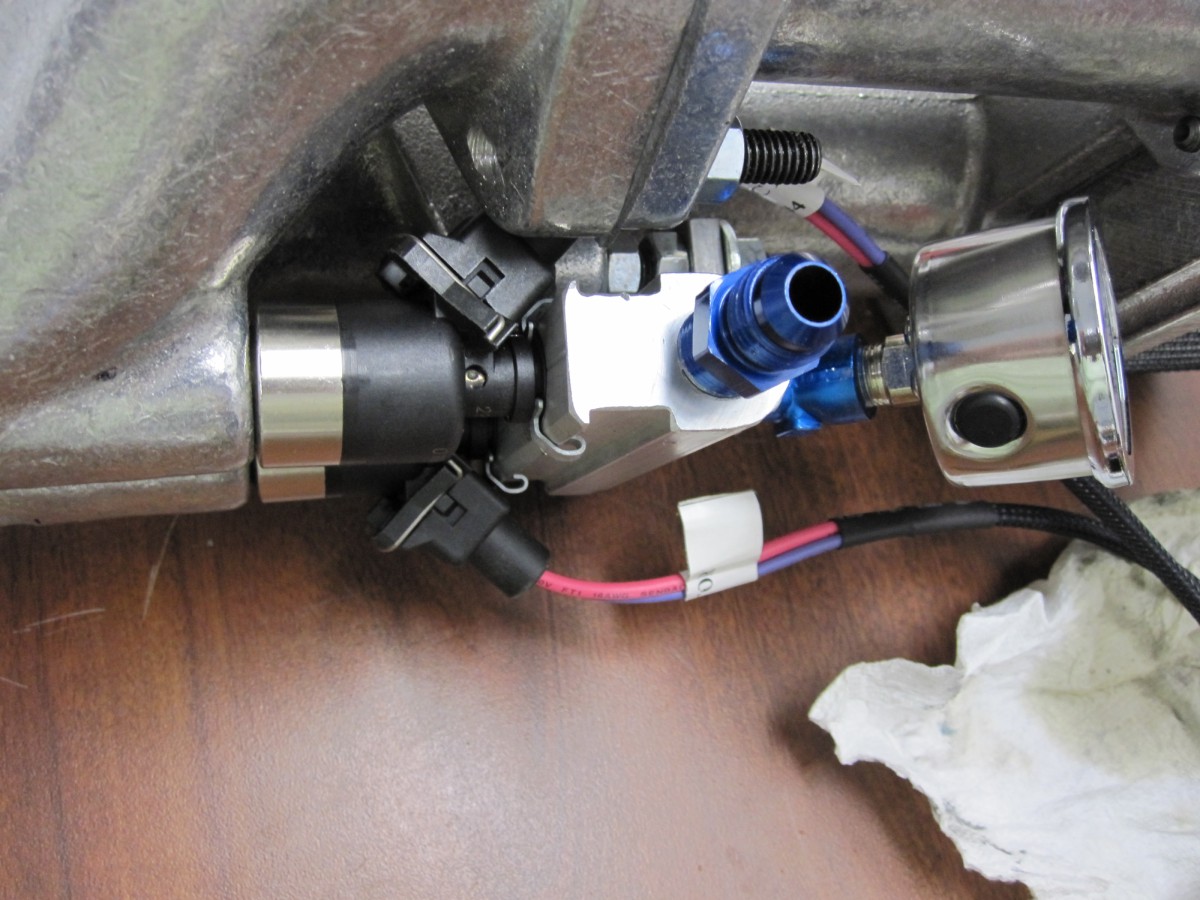
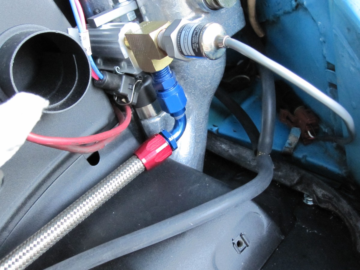
Close-up view of the fuel pressure sensor mounted on the end of
the fuel rail.
Magnecor KV85 spark plug wires were installed to minimize
electrical interference.
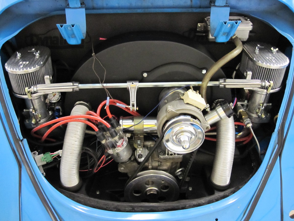
Showing the heater tubes installed and wiring organized.
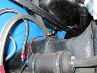
Mounting for the fuel pump and fuel filter. Also see new brake
fluid reservoir.
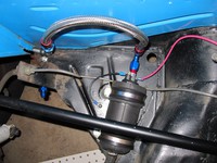
Close-up view of fuel pump connections.
Zip-tied fuel filter. Hard to mount without kinking the hose.
The fuel tank gets a T fitting for the supply and return lines.
Braided hose and AN fittings are nice to work with!
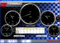
Quick-Tune software running on my laptop, with engine running. Now
the tuning begins!
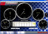
Playing with the Air-Fuel Ratio (AFR) settings in Quick Tune
software.